
If it can't be done in the pcb design tool, you probably won't need it as it is fab related. problems User selectable 2020 -11 -28 CAM 350 Product Overview 12. Of course, the question is : do you need that ? A pcb fab does, but a pcb designer doesn't. Boolean operations between layers / entities. It's going to be either Ucam or Genesis (frontline) you can do things like pattern shrinking or expansion to compesate for etching, all kinds og logic operations on layers, converting flashes to strokes and reverse, converting polygons to strokes or meshes to polygons and much much more. DownStream CAM350 DFMStream 14.5 & BluePrint-PCB 6.5 full.
CAM350 12 ARCS DOWNLOAD
Jeremy Corbyn - Wikipedia Download DownStream CAM350 DFMStream 14.5 & BluePrint-PCB 6.5 full. Go to any pcb fab and ask them what they run to do their fab processing. ARC Reports for UPSC - Download PDFs of Important - BYJUS Hier sollte eine Beschreibung angezeigt werden, diese Seite lässt dies jedoch nicht zu.

One of the main features supported in version13 is track ‘arcs’ which will be converted to straight lines - this does not affect the integrity of the information.

They own the standard Ucam is the direct descendant from the Gerber corporation, sold to intergraph, then to Barco thento Mania and now incorporated as UcamCo. If the File begins 12345 2 39 this is Version 13, in this case the file will need to be converted using free-issue files from Vutrax to downversion to version 12 or version 11. I know CAM350 also has problems with certain gebrer features ( complex polygons and some arcs ).
CAM350 12 ARCS SKIN
If the distance between the solder mask and the large copper skin is not enough, you can copy the enlarged solder mask (to meet the process capability) Go to an empty layer, delete the solder mask corresponding to the large copper skin, and enlarge the remaining solder mask as the second layer.Cam350 is a basic tool where you can indeed do some panelisation work, but it ' nowhere near Genesis or Ucam. The layering method is: first layer (plus layer), second layer (minus layer), third layer (plus In general, in order to reduce the amount of data, we can leave the first layer only with a large copper skin.

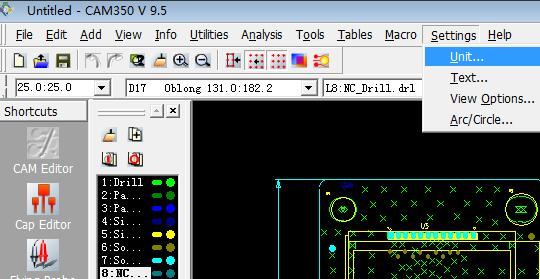
First copy all the PADs of the circuit layer (this layer is the first layer) to an empty layer, delete the PAD corresponding to the large copper skin, and enlarge the remaining PADs to reduce the circuit layer (the second layer) ), And then copy the first layer to an empty layer, and delete the large copper skin as the third class. When the data is covered by a large area of copper foil, the distance between the line or PAD and the copper skin is not within the production requirements, and the appearance size is large, (such as the wide one), the following methods can be used to quickly repair the line or PAD and copper The distance between the skins. All this These settings will be saved in the *. Of course, click a Layer Sets and press Delete to delete the setting, or you can select each of the groups Layer. If you want to edit a layer combination, just click the AdD button and repeat the previous operation. Click the 2 button to add another layer, repeat this process until all The desired layers are added. After OK, the layer will be displayed in the box to the right of the 1 button. If you click the 1 button, a selection box of "Layer List" will pop up. I create the cuts for the eyelashes, in the center of each side of the square. This will create the 2mm groove that will separate the PCB from the panel, secured with 4 tabs made with mouse bites. Next click the number buttons on the right to add each Layer The layers contained in Sets. I make a square of 70 mm on the side and another exterior of 72 mm. Hot Key 1", the surface hotkey 1 has already been used.
CAM350 12 ARCS SOFTWARE
Some of the software listed below are Gerber editor software as well, and let you view as well as make changes to Gerber PCB designs. These software let you open and view Gerber files (GRB files) with the help of their extensive tool set.
CAM350 12 ARCS FREE
Hot Key 1" is displayed in the "Layer Sets" list, but if it has been set in the other three types (Layer Stackup / BlinDanDBuried / MCM Technology), It will automatically start with the next unused hotkey. Here is a list of Best Free Gerber Viewer Software for Windows. The name can be the default or can be defined by yourself, but the name is not Spaces are allowed. fluentairpakv2.1.12linux fluentfidapv8.7.4 fluentfidapv8.7.4linux fluentflowizardv2.0.4 fluentflowlabv1.12 fluentflowlabv1.12 linux fluenticepakv4 fluentmixsimv2.0.2 fluentmixsimv2.0. The name is entered in the "name" box on the right. In the "Layer Sets" list on the left is the name of the layer setting and its assigned hotkey number.


 0 kommentar(er)
